Those are my notes about using the Embedded Pi board with an open source toolchain. Some apply to STM32 in general. The Embedded Pi board has a STM32 microcontroller with Arduino-compatible headers.
<rant> It was obviously designed by people who don’t know the open source toolchain for that chip. If you don’t already have an Embedded Pi, consider buying something else like the ARMinARM or a STM32 discovery board.
Most likely CooCox just wanted to ride the hype around Arduino and Raspberry to push their Windows-based IDE and their “BSD licensed free and open source” operating system for which “No body has the right to sell the software or related products without permission”. (Both quotes are from the CoOS terms and condition.) I’m not going to bother with this stuff in my spare time. This is a board with a STM32 chip on it, and there is an open source toolchain for that chip. </rant>
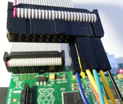
I’m using the Embedded Pi in standalone mode, with the Raspberry Pi acting as a programmer. The provided adapter cable connects only the Arduino-compatible pins, not the pins used for programming. It’s easier to ignore the “RAS-PI” header altogether and just wire up things directly.
There are two programming options:
- JTAG
- STM32 built-in bootloader
JTAG is prefered because it allows debugging. The STM32 built-in bootloader allows to flash over a serial interface, which is a simpler protocol. I will describe both ways.
Fancyblink
Here is my fancyblink demo, which blinks the board LED in a sine wave. If you just want a binary for testing, use fancyblink.elf or fancyblink.bin.
I use libopencm3 with the STM32 reference manual close at hand. An alternative may be the mbed SDK based on CMSIS. I compile on Linux (Debian sid). The compiler was installed with:
apt-get install gcc-arm-none-eabi gdb-arm-none-eabi
You could also compile on the Raspberry Pi, at least the ARMinARM people seem to have that working.
JTAG
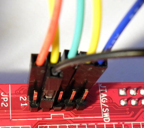
Hardware setup:
By default the JTAG connector can only be used for SW (serial wire). Currently support for SW in OpenOCD is experimental, but support for JTAG is stable. Solder the bridge to connect the TDI JTAG pin, as described in the Embedded Pi User Manual. Keep in mind that Arduino pin 8 will not be accessible from the STM32.
| JTAG Header | Pi Header |
|---|---|
| 3 (GND) | 25 (GND) |
| 4 (TCK) | 23 (GPIO11/SCLK) |
| 6 (TDO) | 21 (GPIO9/MISO) |
| 8 (TDI) | 19 (GPIO10/MOSI) |
| 2 (TMS) | 22 (GPIO25) |
| 10 (RESET) | 18 (GPIO24) |
Note that JTAG pin 10 is the system reset (SRST, not TRST) which is connected to the reset button.
Software setup:
I’m using raspbian on the Pi, which has an OpenOCD package. But it doesn’t have the fast GPIO driver (bcm2835gpio).
Installing:
sudo apt-get build-dep openocd
sudo apt-get install git
git clone git://git.code.sf.net/p/openocd/code openocd
cd openocd
./bootstrap && ./configure --enable-bcm2835gpio && make
sudo make install
Running:
sudo openocd -f interface/raspberrypi-native.cfg \
 -c 'bcm2835gpio_srst_num 24' \
 -c 'reset_config srst_only srst_push_pull' \
 -f target/stm32f1x.cfg
You may get messages like:
Error: JTAG scan chain interrogation failed: all ones
Warn : Invalid ACK 0x7 in JTAG-DP transaction
which means you got the wires wrong. OpenOCD will run anyway, but don’t be tempted to continue. Go fix your wiring.
OpenOCD is now in server mode, waiting for a debugger connection. You only wanted to flash? No problem. Add yet another argument:
-c 'program fancyblink.elf verify reset'
or
-c 'program fancyblink.bin 0x08000000 verify reset'
For debugging, I’m running gdb on my Debian PC:
arm-none-eabi-gdb fancyblink.elf
on the gdb prompt:
target remote raspberrypi:3333
load
continue
You can put some commands into a .gdbinit file for convenience. And, of course, create a shell script for the lengthy openocd invocation. Also, if you connect via ssh, use ‘ssh-copy-id’ instead of typing a password every time.
STM32 built-in bootloader
- Disable the Linux system console on the Raspberry Pi. Edit /boot/cmdline.txt and /etc/inittab to get rid of all usage of ttyAMA0.
- Compile stm32flash on the Raspberry Pi.
- Do not use stm32load.py. It works, but its error handling is broken. You get messages like “None” and “NONE”. Stm32flash is more mature, it prints chip information and can drive GPIO pins so you don’t have to push RESET.
- Wire it up.
| Label (Embedded Pi) | Pi Header |
|---|---|
| GND | 25 (GND) |
| RESET | 18 (GPIO24) |
| 28 | 8 (GPIO14/TXD) |
| 26 | 10 (GPIO15/RXD) |
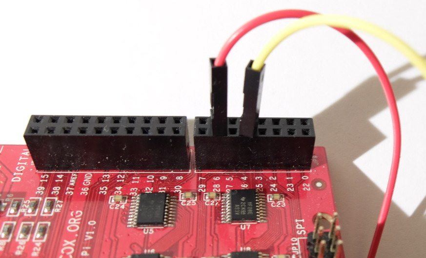
Also connect the BOOT0 to 3V3 on the Embedded Pi. Theoretically you can push the RESET and BOOT0 buttons. But often the bootloader seems to be stuck answering at a low baud rate. It’s more reliable (and easier) to let stm32flash drive RESET.
Flash, Verify, Run:
stm32flash -b 115200 /dev/ttyAMA0 -i -24,24 -w fancyblink.bin -v -R -g 0
Warning: when you execute the flashed program with the “-g” command, interrupt handlers will not work (if you use them). You have to add
SCB_VTOR = 0x08000000; // point irq vector to flash
to your startup code. Otherwise execution will jump into the bootloader’s interrupt handler at the first IRQ and most likely never return. You could also release BOOT0 and then reset to solve this problem by starting directly from flash.